No products


SchoolBus GPIO Board
sbgpio
New product
The aim of this board is to let you learn basic input output functions in electronics.
This product is no longer in stock
More info
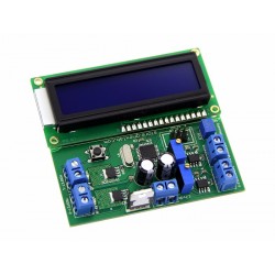
The aim of this board is to let you learn basic input output functions in electronics. For advance makers you can use this board for user interface purposes. The buttons may help you to select a menu item on the LCD and the RGB led on the board can be a wifi connection status indicator.
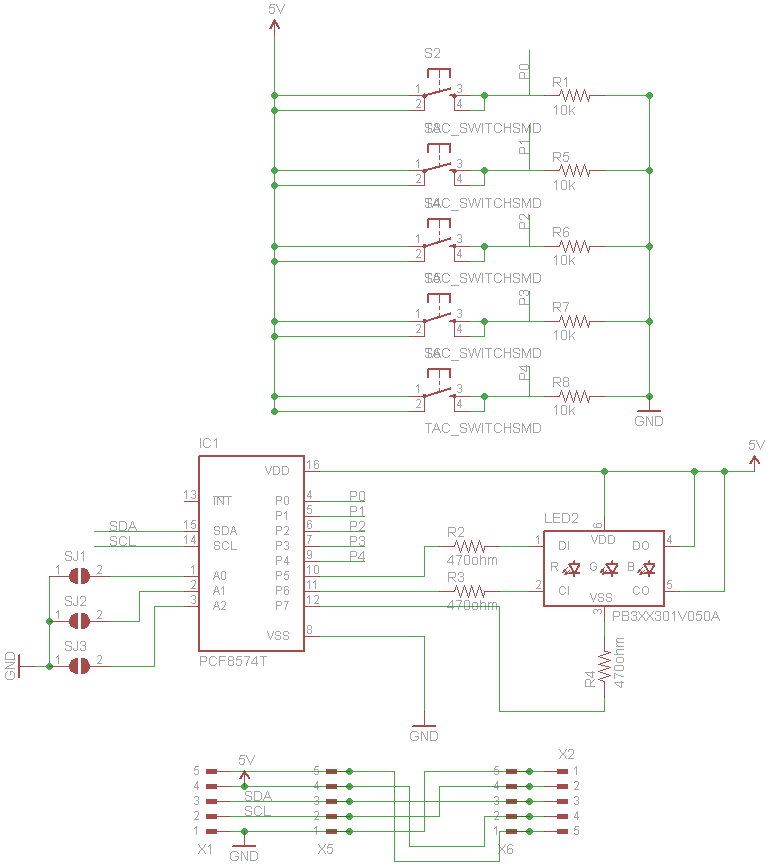
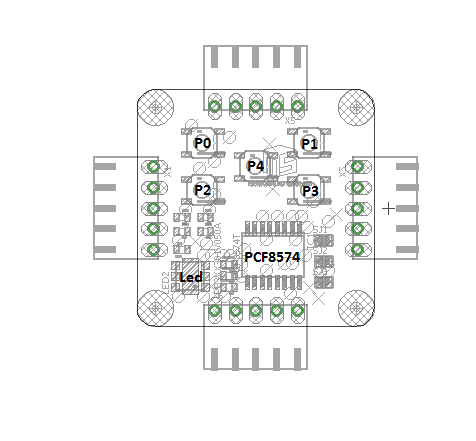
This board has five buttons and one RGB led on it. For the I2C communication there is one pcf8574 ic. This chip is 8-bit input/output (I/O) expander for the two-line bidirectional bus (I2C) is designed for 2.5-V to 6-V VCC operation. The PCF8574 device provides general-purpose remote I/O expansion for most microcontroller families by way of the I2C interface [serial clock(SCL), serial data (SDA)].
If you find this technical listen to this. You have 8 pins to control as input and output. Input means you will listen the pin and understand if it is 1 or 0. Output pin is you can write 1 to it to make it high. For example a LED will light on. If you write 0 to an output pin the led will turn off. You have 8 of these pins on the IC that you can control them as input pin or output pin. On the board the five buttons connected to the 0-4 pins of the IC. (look at the schematics below). Assume that you press the P0 button. You will read 1 from the software for that pin. You have to think in Binary. Every pin has its own bit in 8 bit Boolean number.
All pins are map as binary numbers. Pressing the button makes the connected pin of the IC high so you get the binary representation of it. Pressing button P1 and P4 will send 2+16 = 18. So every combination of the buttons have an integer value in software.
So what about the RGB led. RGB, or red-green-blue, LEDs have three dierent color-emitting diodes that can be combined to create all sorts of colors. Depending on how bright each diode is, nearly any color is possible! RGB led has 3 led in one package. One red, one green and one blue led are connected to 5,6,7 pins of the IC. To get a red color you have to write 0 to that pin. Why 0 instead of 1? Please take a look at the schematics. One side of each led is connected to the power source 5V. If you set the other end of the led which is pins of the IC, you can not generate a voltage difference so a voltage flow. If you set this pin as 0 the voltage from 5V can flow through the 0 level. This is a voltage difference. Something like a water flow from mountain top to the foothills. So you can light on!
Take a look at the software part on how we set the pins to get the light of different colors.
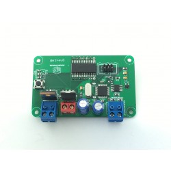
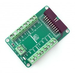
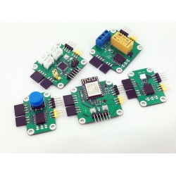
GPIO Board Components
GPIO Board Schematics